Principles
Copyright 2009
Principles
Computed tomography is an imaging technique where X-ray technology and computer technology are used to produce transverse or axial tomograms of the body. X-ray generators and detectors are positioned in a doughnut type ring around the body. The X-ray generators produce highly collimated X-ray beams which interact with the tissue from many different angles and the result is detected and recorded by the detectors that are aligned in a ring oppposite the generators. Each tissue has specific attenuation characteristics. The attenuation of the x-rays of a specific tissue obtained from multiple projections is collected by a computer which organizes and displays the information using mathematical algorithms.
|
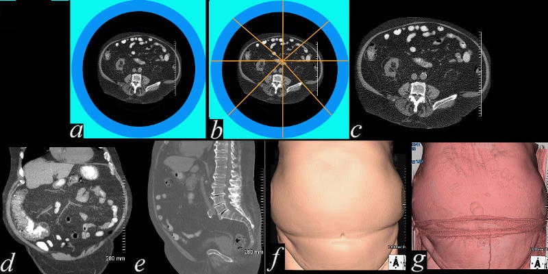
Interrogating the Body from Multiple Angles |
| 71194c01c02.800 approach to learning CT scan pixel interrogation X-ray detector multiplicity principles Cushings disease underpants coronal sagittal axial transverse 3D volume rendering CTscan learning multifaceted understanding manipulation reconstruction Davidoff MD |
The components of a CT scanner include an X-ray tube, an X-ray limiting component that limits the beam thickness, an X-ray detector, a storing unit and a processing unit.
Source of the X-rays -X-ray tubes
X-ray tubes provide the source of the X-ray beam. The maS and Kv are a measure of the strenghth of the X-ray
CT Imaging Parameters
maS
The mAs is directly proportional to the number of photons in an X-ray beam and is a measure of the intensity of the beam. The higher the maS the less noise or quantum noise there is in the image. ie there is an an inverse relationship of maS with quantum noise. This means that the higher the maS the better the contrast resolution but the higher the radiation dosee to the patient and the higher the load on the X-ray tube.
kV
The kV is defined as the average peak energy of the X-ray beam. Thus the higher kV the higher is average peak energy. Like maS the kV is inversely proportional to quantum noise proportional to patient dose, but can decrease contrast resolution
Beam Collimation and Collimation Thickness
Beam collimation refers to the thickness of the X-ray beam and it is controlled by filters. As a result of collimation scatter radiation is reduced. Collimators control slice thickness by controling the voxel size. They are positioned both at the x-ray tube and near the detectors.
The thinner the beam the less volume averaging and the better the spatial resolution. The better the spatial resolution the better, the less artifacts are produced and the better the 3D reconstructions. However with thinner collimation there is more noise, less contrast resolution, and increased scan time.
Slice Reconstruction Increment
This is the distance between two slices that are reconstructed from a volumetric data set. If the the beams overlap as they rotoate over two spirals detection of small lesions is improved. When the axial images are used for reconstruction the more the overlap the better te reconstruction. Radiation exposure however is increased.
Rotation Time
Rotation time is the time for one 3600 rotation. The current rotation time is below a second allo9wing for physiological imaging.
Pitch
Pitch is the ratio of table speed per 360 degree gantry roatation to beam collimation. the higher the pitch the faster the scan time but also the lower the radiation.
Tissue Attenuation
Each tissue has characteristic manner in which it reacts with X-rays and the term tissue attenuation reflects the characteric interaction of tissue with X-rays. For some tissues (like cotrtical bone) the X-ray will be almost totally reflected, for others it will have variable reflection and transmission (soft tissue water), while for others the X-ray will pass right through without interaction (air). Bone has a high tissue attenuation and air a low attenuation.
Detection
Scintillation detectors based on photo diodes measure the energy of the exiting beam . Xenon gas ionization chambers werte previously used as detectors.
CT Density Scale in Hounsfield Units
Air -1000 black
Fat -100HU light black
Water 0HU dark gray
Soft Tissue about 20-60HU light gray
Calcification +1000 white
cancellous bone +400HU
Bone of the cranium +2000 Hu
Image Reconstruction
The CT technique divides the body into pixels and the pixel is assigned a number calculated by the sum of all the interrogations of that pixel. The linear attenuation coefficient (μ) quantitates the character. The CT numbers are derived by using the coefficient of water (HU = 0) and the attenuation coefficient of the pixel. The Mathematical algorithms are used to reconstruct the images. The most commonly used algorithms are back projection, iterative methods and analytical methods.Smooth algorithms are used chestimaging to smooth out the borders of the mediastinum against the lung. Lung algothirithms on the other hand are used for visualizing the air filled alveoli that do not attenuate the X-rays against the soft tissue of the interstitium.
Multiplanar reconstruction in the sagittal and coronal plane are routine parts of the examination. The maximum intesnsity projection (MIP) or minimum intensity projection technique can be used to enhance either high density or low density in the reconstruction algorithms.
Oblique reconstructions or curved reformats can also be applied to reconstruct the axial images
Surface rendering uses a threshold density to enable edge detection, and recreate images in 3D, but only the surface is visible and not the inside of the structure.
Volume rendering facilitates seeing through the surface by making the surface densisties transparent
Matrix
Matrix is the number of pixels in the image in the x and y axis, typically 512X512 but ranging from 340X340 764X764 up to 1024X1024
MDCT
Multislice detector technology is the utilization of multiples of beams detectors and collimators positioned in multiple rings within the larger doughnut so that for a given single rotation more volume of tissue is interrogated in shorter time. This leads to less artifact created by physiological movement (breathing heartbeat), more data collected per unit time, and improved spatial and contrast resolution. On the other hand it results in more radiation. In MDCT technology the table moves and the beam assumes a helical course
Resolution
Resolution reflects the ability to distinguish two components of a structure. It may be the difference in size, shape, position (spatial resolution) or character (contrast resolution). In the case of two different moments in time for a structure – eg a heart beat – the ability to resolve the event at two different sequential events accurately is called temporal resolution.
There are many factors that affect resolution. For example resolution can be adjusted by changing the size of the focal spot (a smaller focal spot size means higher resolution) and using collimators in front of the X-ray detectors after emerging from the patient. This would improve spatial resolution but result in greater quantum noise.
By allowing for volumetric acquisition of data, MDCT technology has vastly improved spatial and temporal resolution.
Resolution is a reflection of how the technology is able to resolve the true characteristics of a structure. There are three major forms of resolution; spatial reaolution, contrast resolution, and temporal resolution.
References
Mahesh M MS PhD FFAAPM MDCT Physics The Basics – technology, Image Quality and Radiation Dose Wolters Kluwer Lippincott Williams Wilkins Philadelphia 2009